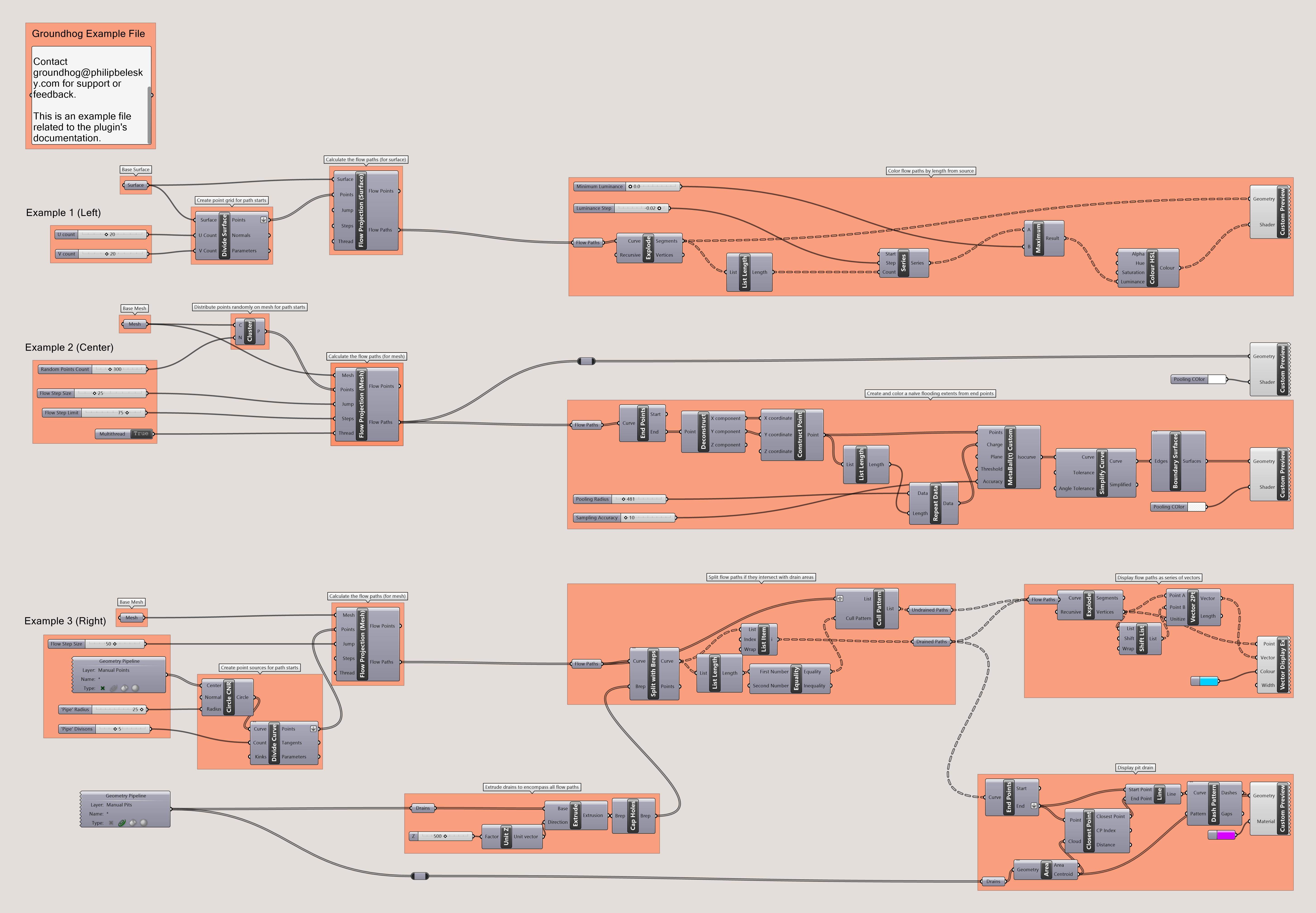
The associated model and definition demonstrating the use of these components can be downloaded here.
Flow Paths
Components for creating projections of surface water flows.

Surface water flow paths across a littoral region
Image via Philip Belesky for the “Processes and Processors” project (http://philipbelesky.com/projects/processes-and-processors/)Flow Paths
The “flows” components create naïve projections or simulations of overland surface water flows and provide methods to analyse the results of these calculations.
The key component — the FlowPath — accepts a series of ‘drop points’ on a Surface or Mesh that become the starting locations of each hypothetical flow path. These starting points then act as the origin points in an ongoing behaviour loop:
- The origin points each sample the surface or mesh to determine its slope
- This sampling identifies a vector that points ‘downhill’
- Each point is then moved along this vector a pre-specified distance and a new point created
- A line is drawn between the origin points and their new points
- The new points are assigned as origin points and the process repeats
The line segments created by this process are ‘grown’ through this series of descending jumps. This ‘gradient descent’ process repeats until a path crosses the edge of the form, a specified quantity of iterations are performed, or until the algorithm determines that there is no further downhill path. This halting calculation aims to identify a ‘basin’ where water might collect and pool rather than continue to flow downhill.
The component then produces as an output a series of Polylines, from which the beginnings, ends, and individual segments can be readily extracted. The process provides degrees of flexibility. By accepting any given set of Points (rather than enforcing a spatial grid or other formation) it offers the ability to work across a number of contexts, from situations where you may want to simulate a uniform distribution (say rain) or just a particular point-source of water.
The FlowPath component takes two forms a SurfaceFlowPath and a MeshFlowPath depending on the geometric type of the ‘landscape’ you want to test.
Construct flow paths over a surface or mesh
| Mode | Name | ID | Description | Optional | Type |
|---|---|---|---|---|---|
| Surface or Mesh |
S or M
|
Base landscape form (as a surface or a mesh) for the flow calculation |
SurfaceParameter or MeshParameter
|
||
| Points |
P
|
Start points for the flow paths. These should be above the surface (they will be projected on to it) |
PointParameter
|
||
| Fidelity |
F
|
Amount to move for each flow iteration. Small numbers may take a long time to compute. If not specified or set to 0 a (hopefully) sensible step size will be calculated. |
NumberParameter
|
||
| Steps |
L
|
A limit to the number of flow iterations. Leave unset or to 0 for an unlimited set of iterations |
IntegerParameter
|
||
| Thread |
T
|
Whether to multithread the solution (this can speed up long calculations) |
BooleanParameter
|
||
| Flow Points |
F
|
The points of each simulated flow path ‘jump’ |
PointParameter
|
||
| Flow Paths |
C
|
A polyline linking each of the flow points into a path |
CurveParameter
|
Workflows and Examples
Once calculated, these flow paths can then be used as inputs for two further components:
The example file for this component demonstrates a number of options for visualisation and extension, such as:
- Using a
Metaballcomponent to display (a very crude) ‘pooling’ effect at the end of the flow paths - Using geometric intersections to test how drainage pits intercept water flows
- Fading the color of the paths as they travel further from their ‘source’


Grasshopper definition for the flow paths definition.
Philip Belesky, for https://groundhog.philipbelesky.com